GEMINI PMX20
SETUP
STEP 1 : CONNECTIONS
- Connect your amplifier of a pair of amplified speakers to one of the XLR/RCA Master Outputs at the rear panel.
- Connect the USB socket at the rear panel of the PMX20 to a USB port of your computer, using standard USB cable
- Optionally connect your CD Players/Turntables or any other analogue source to the CH1 to CH4 Input sockets at the rear panel
- Connect the PMX20 to an AC Plug and power on the unit, after all connections are made.
STEP 2 : DRIVERS & FIRMWARE
Drivers :
For Windows computers, download and install the Gemini ASIO drivers from https://geminisound.com/pages/downloads
No drivers is required to be installed for Mac OSX computers.
Firmware : Make sure your unit is updated to the latest firmware from https://geminisound.com/pages/downloads
STEP 3 : VirtualDJ Setup
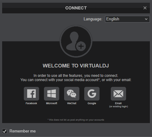
Once VirtualDJ is opened, a Connect Window will appear to enter your account credentials.
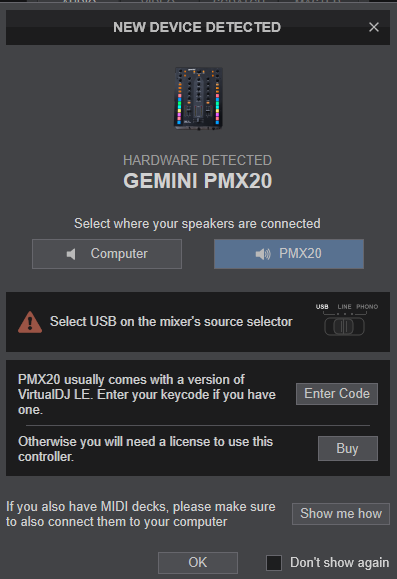
A Pro Infinity or a Pro Subscription License is required to fully use the Gemini PMX20. Without any of the above Licenses, the controller will operate for 10 minutes each time you restart VirtualDJ.
http://www.virtualdj.com/buy/index.html
The Gemini PMX20 is also operating with the bundled VirtualDJ Limited Edition., which also allows DVS (see Advanced Setup)
Click on the "PMX20" button if your speakers are connected to the Master Output at the rear panel of the PMX20.
You can still make changes in the Audio setup from VirtualDJ Settings->AUDIO tab.
An additional Enter code button will be available, if your Account does not offer a Pro or Plus License or you have skipped the Login process.
Click on this button and enter the Keycode (serial) of your VirtualDJ LE.
On the PMX20, use the MIDI/USB buttons on each channel to enable the Midi operation.
Make your selections and press OK.
The unit is now ready to operate.
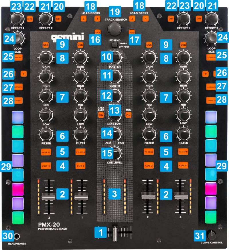
TOP PANEL CONTROLS
CONTROL
ACTION
When the SAMPLES buttons is pressed, use this button to select the next available Sampler Trigger mode (on/off, hold, stutter and unmute)
While the SAMPLER button is pressed, use this button to load and select the next available Sampler Bank
When focus is on Folders list, push to set focus to the Files/Tracks List.
While the SAMPLER button is pressed, use this encoder to adjust the Sampler Master Volume
When the FX Param mode is enabled (EFFECT 1 - ON is on) use this knob to select the Effect for the Left/Right assigned Deck
Use the left-side button 1 to assign Deck 1 as Left deck
Use the left-side button 3 to assign Deck 3 as Left deck.
Use the right-side button 2 to assign Deck 2 as Right deck
Use the right-side button 4 to assign Deck 4 as Right deck.
In Sampler mode : Use the pads to trigger samples 1 to 8 from the selected Sampler Bank. Depending on the selected Trigger mode, you may find useful to stop a playing sample, by holding down the SAMPLES button and pressing the related pad.
REAR PANELS
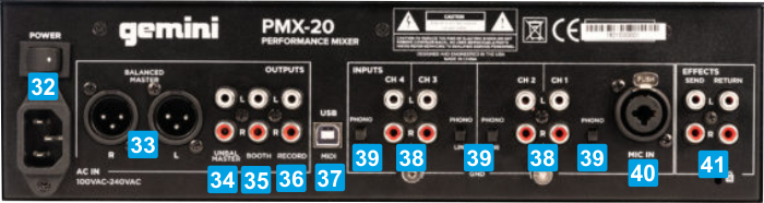
CONTROL
ACTION
- VirtualDJ (or other supported application) is not running (stand-alone)
- VirtualDJ is running, the PMX20 is set to Hardware (Mixer) mode and the USB buttons are turned off
- VirtualDJ is running with Timecode inputs set in Audio Setup (signal of the Timecode sources) will be muted from output and will be routed to VirtualDJ for DVS control.
This procedure is not operated by VirtualDJ
ADVANCED SETUP
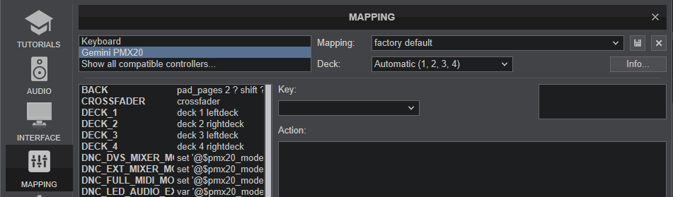
MIDI MAPPING
The unit should be visible in the CONTROLLERS tab of Config and the “factory default” available/selected from the Mappings drop-down list. The factory default Mapping offers the functions described in this Manual, however those can be adjusted to your needs via VDJ Script actions.
Read further details at
http://www.virtualdj.com/manuals/virtualdj8/settings/controllers.html
http://www.virtualdj.com/wiki/VDJ8script.html
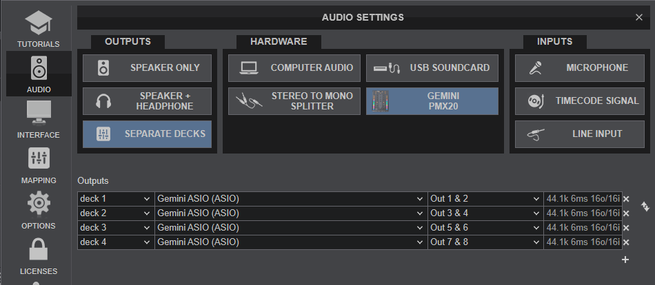
AUDIO Setup
Default Audio setup
The unit has a pre-defined Audio setup and a special button in the AUDIO tab of Config to provide that.
If the pre-defined audio setup is selected, speakers and Headphones need to be connected to the unit at the rear and top side panels respectively.
MIXER MODES
The Gemini PMX20 can operate in 3 modes, the MIXER (Hardware) mode, the DVS mode and the MIDI (Software) mode.
MIXER MODE
This mode is the default and auto-selected on every power-cycle. In this mode, the audio mixing (Volume, Equalizer, Filter and Crossfader) is performed by the PMX20. All the previously mentioned mixer elements, will still send Midi signal, thus the corresponding elements on the GUI of VirtualDJ will follow the movements and positions of the hardware ones. However, the GUI elements will not control the mixing (fake mixer mode). The Audio Interface of this mode is 8 channels out, without any input channels, so no DVS control is offered in this mode.
Every mixer channel can have a VirtualDJ or an external device (connected to the CH Inputs at the rear panel) as source, selected by the USB buttons at the top panel.
When the USB button is turned on (led is lit), the audio signal from the respective VirtualDJ will be passed to the PMX20 channel.
When the USB button is turned off (led is off), the audio signal from the external source will be passed to the PMX20 mixer channel and the respective VirtualDJ deck will be muted.
Up to 4 VirtualDJ decks can be controlled from the PMX20 in the Mixer mode.
MIDI MODE
In this mode, the audio mixing (Volume, Equalizer, Filter etc) is performed by VirtualDJ and a different sound card (other than the builtin of the PMX20) can be used as well. The USB Audio interface of the PMX20 does not offer Timecode/DVS Inputs in Midi mode and up to 4 VirtualDJ Decks can be controlled from the PMX20.
The external sources (connected to the CH Inputs at the rear panel) cannot be used in the Midi mode and the USB buttons will remain on.
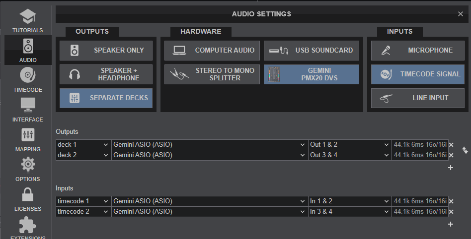
TIMECODE/DVS MODE
In this mode the USB Audio Interface of the Gemini PMX20 turns into 4out/4in channels, offering control of 2 VirtualDJ Decks (the middle ones) along with DVS/Timecode controls. The outer PMX20 mixer channels 3 and 4 can be used to route signal from externlal sources, but cannot control any VirtualDJ Deck.
Note: Timecode control requires one of the following licenses..
- Pro Infinity
- Timecode Plus license
- Limited Edition keycode (serial) of Gemini PMX20 (comes with a special Timecode additional license - which requires online login for the extra license to be validated, at least once).
How to switch between the 3 modes
Hold down the USB/MIDI button on Channel 3 (first from left) for more than 4 seconds (will blink for a while) and then release for the Mixer (default - Hardware) mode to be selected.
Hold down the USB/MIDI button on Channel 1(2nd from left) for more than 4 seconds (will blink for a while) and then release for the DVS mode to be selected.
Hold down the USB/MIDI button on Channel 2 (3rd from left) for more than 4 seconds (will blink for a while) and then release for the Midi (Software) mode to be selected.
Each time a selection of a Mode is made, VirtualDJ will automatically apply the necessary Audio setup for the selected mode.
Important Do not change the Audio Setup manually, unless you are certain of the selected mode. Prefer to allow VirtualDJ to automatically set it up for you when the mode is selected via the long-press of the USB buttons as described above.
RECORDING
When mixing with VirtualDJ, your mix can be recorded in the following cases.
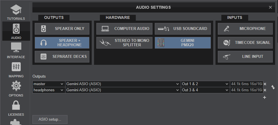
- The PMX20 is set to Software/MIDI mode. In this case (with Master & Headphones as Audio setup), all you need to do is to use the REC button in the MASTER Mixer panel of VirtualDJ GUI to record your mix. However, the Microphone input of the PMX20 will not be recorded
- The PMX20 is set to Hardware(MIXER or DVS) mode. In this case, you will need to route the Master Output from either the BOOTH or REC Output to an Input of another USB Audio Interface and add a record line in your Audio setup.
In the following example, we have connected the REC Output with the Input of a USB Audio Interface using standard 2xRCA to 1/8" stereo jack, and we have added a record line using the input of that sound card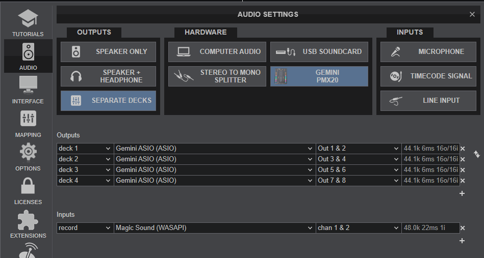
Hardware mode - Audio setup with external Recording Input
Note that in case of recording externally (using the REC OUT routed to a different sound card), all inputs (from CH1 to CH4 sources) and the Microphone of the PMX20 will be also recorded along with your mix
For further software settings please refer to the User Guide of VirtualDJ 8. http://www.virtualdj.com/manuals/virtualdj8/index.html
